Educated Climber.com

  • Start Here
  • Content
    • Tree Climbing Basics
    • Tree Work Basics
    • Professor Ed Gilman Teaching Series
    • Knots
    • Rigging Basics
    • Chainsaw Basics
    • Basic Jobsite Skills
    • Pests and Diseases
    • Tree ID
    • Small Business Resources
    • Additional Resources
  • Podcast
  • Blog
  • Shop
  • Subscribe

The Ashley Book of Knots

May 2, 2017 By patrick@educatedclimber.com 12 Comments

– source: Wikipedia

“A knot is never “nearly right”; it is either exactly right or it is hopelessly wrong, one or the other; there is nothing in between. This is not the impossibly high standard of the idealist, it is a mere fact for the realist to face.” – Clifford Ashley


Published in 1944, this is the Bible of knots. Clifford Ashley took notes on knots for over 40 years of his life, and then labored for over 11 years to produce the most comprehensive reference of knots and ropework ever written. Knots in books and articles around the world are frequently referenced back to Ashley’s book. Citations to Ashley numbers are usually in the form: “The Constrictor Knot (ABOK #1249)” or just “ABOK #1249”.

With almost 4000 knots, his work covers basically every type of hitch, bend, stopper knot, lashing, binding knot, and running knot that you can imagine, as well as decorative and fancy knots, trick and puzzle knots, sinnets, marlingspike, and 3-strand splices, among many, many others. This book is exhaustive, and a testament to a devotion and drive to produce something that would stand the test of time. In addition to showing you how to tie the knots, which were all painstakingly illustrated by the author, Ashley helps to explain the history and usage of the knots. The first chapter, ‘On Knots’ is a fascinating look at the history and tools of sailors and ropeworkers – highly recommended reading.

From the first chapter:
“To me the simple act of tying a knot is an adventure in unlimited space. A bit of string affords a dimensional latitude that is unique among the entities. For an uncomplicated strand is a palpable object that, for all practical purposes, possesses one dimension only. If we move a single strand in a plane, interlacing it at will, actual objects of beauty and of utility can result in what is practically two dimensions; and if we choose to direct our strand out of this one plane, another dimension is added which provides opportunity for an excursion that is limited only by the scope of our own imagery and the length of the ropemaker’s coil.
What can be more wonderful than that?”

This book is truly a must-have for professionals who use rope everyday. Of particular note for tree climbers:
From Wikipedia: “The Ashley Book of Knots was compiled and first published before the introduction of synthetic fiber ropes, during a time when natural fiber cordage – typically twisted, laid, or braided rope – was most commonly used. The commentary on some knots may fail to address their behavior when tied with modern synthetic fiber or kernmantle style ropes.”

Clifford Ashley died in 1947. His book is now in the public domain.

The Ashley Book of Knots is available in hardcover from Amazon.com here.


the ashley book of knots archive-org
Download as PDF


source: archive.org


Climb High, Work Smart, Read More.

-TreeMuggs

I would love to hear from you. Please send all comments/questions/hatemail  to patrick@educatedclimber.com


Filed Under: Knots

Ropes, Knots and Climbing: National Park Service Bulletin, 1955

April 17, 2017 By patrick@educatedclimber.com 16 Comments


“It may be truthfully said that the ability to perform efficient work in a tree is based firmly upon a thorough working knowledge of rope, knots, splices, hitches, and climbing technique. No tree worker can be considered skilled unless he possesses such basic knowledge and knows how to apply it properly.

Real skill with rope comes only with proper instruction and constant practice and cannot be obtained merely through reading. It is hoped, however, that this bulletin will serve a useful purpose in explaining some of the fundamentals of rope, knots, and climbing, and that it may be helpful up to a certain point in actual practice.”

– A. Robert Thompson, Forester, National Park Service


Ropes Knots and Climbing – National Park Service 1955
Download as PDF


Climb high, Work smart, Read more.
– TreeMuggs

I would love to hear from you. Please send all comments/questions/hatemail to patrick@educatedclimber.com


Filed Under: Back To Basics

MNR Publication: Common Pests of Trees in Ontario

April 10, 2017 By patrick@educatedclimber.com 4 Comments


Pests of Trees in Ontario
Download as PDF


Climb high, Work smart, Read more.
– TreeMuggs


I would love to hear from you. Please send all comments/questions/hatemail to patrick@educatedclimber.com


Filed Under: Back To Basics

Chlorosis

April 10, 2017 By patrick@educatedclimber.com 6 Comments


photo courtesy of Washington State University

Chlorosis is a condition in which leaves produce insufficient chlorophyll. As chlorophyll is responsible for the green colour of leaves, chlorotic leaves are pale, yellow, or yellow-white. The affected plant has little or no ability to manufacture carbohydrates through photosynthesis and may die unless the cause of its chlorophyll insufficiency is treated.

Chlorosis is typically caused when leaves don’t have enough nutrients to synthesise all the chlorophyll they need. It can be brought about by a combination of factors including:

  • a specific mineral deficiency in the soil, such as iron;
  • a high soil pH (alkalinity) at which minerals become unavailable for absorption by the roots
  • poor drainage (waterlogged roots)
  • damaged and/or compacted roots
  • pesticides and particularly herbicides may cause chlorosis, both to target weeds and occasionally to the tree being treated.
  • exposure to sulphur dioxide

The lack of iron is one of the more common nutrients associated with chlorosis. Manganese or zinc deficiencies in the plant will also cause chlorosis. The way to separate an iron deficiency from a zinc or manganese deficiency is to check what foliage turned chlorotic first. Iron chlorosis starts on the younger or terminal leaves and later works inward to the older leaves. However, manganese and zinc deficiencies develop on the inner or the older leaves first and then progress outward. Plants need iron for the formation of chlorophyll.  Iron is also necessary for many enzyme functions that manage plant metabolism and respiration. Iron becomes more insoluble as the soil pH climbs above 6.5 to 6.7.  With most plants, iron can only be absorbed as a free ion (Fe++) when the pH is between 5.0 and 6.5.  Other elements such as calcium, zinc, manganese, phosphorus, or copper in high amounts in the soil can tie up iron so that it is unavailable to the plant. However, a shortage of potassium in the plant will reduce the availability of iron to the plant. Insufficient iron in the soil is also (although much less frequently) a problem.


CONTROL

If an immediate result is desired, then a foliar application of ferrous sulphate is needed. Ferrous sulphate should be applied at a rate of 1 oz./gallon of water with a few drops of dish soap added. This method of application allows for the absorption of iron directly by the leaves and results should be seen within ten days. The application of iron chelates or sulphur directly to the root zone is another method of treatment. Results are slower to appear but can last for one to two seasons. The rates of application are on the package. Finally, the soil can and should be amended if iron chlorosis has occurred. Working peatmoss, compost and/or well-rotted manure into the vicinity of the tree or shrub well increase the availability of essential minerals and nutrients. If the iron chlorosis is severe then the combination of the foliar spray and an application of iron chelates to the soil is recommended.


This page was compiled from multiple sources, including the Wikipedia article here, and the University of Illinois Extension office here.


Climb high, Work smart, Read more.
– TreeMuggs


I would love to hear from you. Please send all comments/questions/hatemail to patrick@educatedclimber.com


Filed Under: Back To Basics

Mechanical Advantage Explained

April 2, 2017 By patrick@educatedclimber.com 12 Comments

Crane at Prague Castle, photo courtesy of handshouse.org

“Any sufficiently advanced technology is indistinguishable from magic.”
– Arthur C. Clarke


“Mechanical advantage is a measure of the force amplification achieved by using a tool, mechanical device or machine system. Ideally, the device preserves the input power and simply trades off forces against movement to obtain a desired amplification in the output force. The model for this is the law of the lever.”   – From Wikipedia


One of the most common situations that arises in tree work is the need for pulling power. We use ropes to pull tops, pegs, and whole trees, as well as lifting and tensioning sections of limbs and logs. Ropework is fascinating to me. Rope is an ancient tool that has been used for centuries, but its use is a dying art – the average person on the street can barely tie their shoes. Our trade is one of the only groups of people that still uses rope to get work done. Today we are going to explore mechanical advantage and how we can use simple physics to amplify the forces in a rigging scenario.

I have read that a person can pull approximately 60% of their own weight horizontally along the ground in good conditions. So if we need a 500 lb pull to get something done and we have a single groundman who weighs 200 lb and can therefore generate around 120 lb of pull, how can we accomplish this 500 lb pull? The simple answer is that the groundman can go find 4 or 5 good friends who are willing to drop everything and come and help him pull on the rope.


source: Wikipedia

This would be an example of working harder. But working harder isn’t always the answer. For one, we usually don’t have the manpower to simply pull on the rope, and two, it’s, well, hard work. So what if we wanted to work smarter to accomplish the same thing? How could that single groundman get the job done, all by himself? The answer: mechanical advantage.

Mechanical Advantage: The Concept

There are many forms of mechanical advantage, but generally, when we use the term, we are talking about the use of ropes and pulleys (block and tackle) as a means of amplifying forces in a system, allowing us to pull much greater loads than we would otherwise be able to.

All mechanical advantage systems using block and tackle are based on a simple observation:


In order for stickman to hold the weight suspended in mid-air, he must pull down with 100 lb of force. So, if the weight is pulling down with 100 lb of force and the stick man is also pulling down with 100 lb of force, then the total amount of force being exerted on the pulley must be 200 lb. The concept that we are trying to understand and make use of is: where you have a load and an anchor connected by ropes and pulleys, forces can be multiplied at the pulleys. And if forces can be multiplied at pulleys, why don’t we attach a pulley to our load? Using just this simple observation, we can design some amazing hauling systems.

(On a side note: the observation above plays an enormous role in aerial rigging system design using blocks or pulleys, where rigging points are exposed to forces far greater than the weight of the pieces being lowered, even without considering shock-loading. We will explore rigging system design in future articles.)

The simplest use of mechanical advantage involves an anchor point, an input force, and a pulley on the load:

Here we are pulling a load uphill. We have tied our rope to an anchor point, in this case a tree, and then run it through a pulley attached to the load. So in this example, you can see that whatever force stickman pulls on the one side of the rope, from himself to the pulley, that same force is also exerted on the other side of the rope, from the pulley to the anchor. So, for stickman to hold the load steady without it sliding downhill, he only has to pull half the weight of the load, i.e. 50 lb, even though the load weighs 100 lb. This is referred to as a 2 to 1 mechanical advantage, or 2:1 MA. We can calculate it by simply counting how many parts, or legs, of rope are acting on the pulley: in this case there are 2, so we calculate a 2:1 advantage. It’s a very simple concept, but the implications are amazing.

Now, let’s imagine that stickman needs to pull the load right up the hill. You can see that his pulling power is doubled, but you might not have realized that the trade-off  for his newfound strength is that he must pull twice as much rope to move the load. In other words, if the rope were tied directly to the load, you would need to pull the full weight yourself, but for every foot of rope that you pulled, the load would advance by a foot. With this 2:1 MA setup, you only need to pull half as much weight, but to move the load 1 foot up the hill, you must pull 2 feet of rope.  Mechanical advantage always involves a trade-off: pulling distance for pulling power. As Robert Heinlein famously pointed out, TANSTAAFL, – “there ain’t no such thing as a free lunch“.

The Block and Tackle System

source: letoolman.com

The block and tackle system was reportedly invented by Archimedes himself and has been used for centuries for lifting and pulling jobs of all sorts. The block and tackle system builds on the general concepts that we have been talking about, but it goes one step further. A block and tackle uses two pulleys to multiply the forces in the system. One pulley is attached to the load and is referred to as the moving pulley. The other is attached to an anchor point.

The simplest form of a block and tackle system is a 2:1 mechanical advantage setup called a Gun Tackle:

In this setup, the rope “begins” or attaches at the anchor, then runs through the moving pulley, then goes through the anchor pulley. Same as before, let’s imagine we hang a 100 lb weight on that bottom, moving pulley and then we want to hold the weight suspended in mid-air. The bottom pulley is functioning exactly the same as our last example, serving to double the pull on the load. The top, or anchor pulley, serves as a re-direct, allowing us to stand on the ground to pull down on the rope. Without the re-direct up top, we would have to stand on the ceiling and pull upwards to get the 2 to 1 advantage, exactly as we did in our previous example where stickman was at the top of the hill and pulling upwards. So, to hold the weight suspended in the air, we pull 50 lb downwards, which gets re-directed by the anchor pulley up top, and then gets doubled by the moving pulley attached to the load, allowing a 100 lb weight to be held with only 50 lb of input force.

The next example is where things really start to get interesting. What if we used multiple pulleys? Here is a simple example of that, and then I will show the equivalent setup with block and tackle:

In this example, you can see that an input force of only 50 lb can support a load of 150 lb, since each leg of rope acting on the moving pulley is exposed to a 50 lb pull, and there are 3 legs of rope acting on that pulley, 50 x 3 = 150. Pretty amazing, right? Keep in mind that for stickman to hoist the load upwards, he would have to haul 3 feet worth of rope to make the load move 1 foot. Remember, every mechanical advantage system involves a trade-off, pulling distance for pulling power.

The above example can be set up using block and tackle, but instead of requiring two separate pulleys at the anchor, those pulleys are combined into a double pulley. This example is technically referred to as a Luff or Watch Tackle:

Hopefully by this point, you get the concept. We use pulleys and double pulleys to amplify forces. We require an anchor point and a moving pulley attached to the load, and we require an input force. We can calculate the mechanical advantage by counting the number of legs of rope that are acting on the moving pulley, which is the same as calculating the trade-off of pulling distance for pulling power. I don’t want to go into an exhaustive treatise on all the different setups of block and tackle. There are many definitive sources out there that will dig deeper. Instead, I want to now focus our attention on the most common applications of mechanical advantage used in tree work.

Assumptions

You know what they say, never assume, because when you assume, you make an “ass” out of “u” and “me”. However, for our purposes here, we will need to agree on some assumptions just so we can do some basic math.

Assumptions:

  1. all pulleys are 100% efficient, that is to say that friction is nonexistent.
  2. all pulling angles are 180 degrees.
  3. all pulleys and ropes are weightless, and ropes do not stretch.

These assumptions allow us to use nice, easy numbers. In reality of course, no pulley has perfectly zero friction and pulling angles are not always 180 degrees. So, realistically, when we say that a system is 3:1 or 5:1, it never actually is. It might be more like 2.89:1 or 4.73:1. But who wants to tell the new guy, “Hey, go grab the 4.73:1 out of the truck!” Anyway, you see my point. Let’s just agree to make some assumptions this one time.


Common uses of Mechanical Advantage in Tree Work

The use of pulleys is so simple and elegant and yet incredibly powerful. There are many, many ways to use mechanical advantage with ropes and pulleys in tree work, but I am not going to get into all of them. Instead, I want to focus on 4 uses of MA that can come in very handy. Once you understand the concepts involved and you have seen some examples, you will be able to design your own hauling systems, custom-made for the situation. Specifically, I want to look at:

  • 2:1  MA for pulling pegs
  • 3:1  Z-Rig setup
  • 5:1  Fiddle Block/Block and Tackle setup
  • Piggyback/Compound MA systems

Keep in mind that in order to set up any MA system in the field, you will require an anchor point. In residential work, the anchor point is often the limiting factor for using mechanical advantage, we can’t use MA without it. Jerry Beranek covers anchor points very nicely in his Working Climber Series Two, Disc 3. Basically, I define an anchor point as any fixed object that I can say without reservation is capable of withstanding the pulling forces that it will be exposed to. In the case of a pulley being installed on the anchor point, that anchor must be able to withstand many times the force of the pull, since the use of pulleys amplifies the forces. So, to set up MA systems in the field, you must have access to a bomber anchor point. Do not assume that an anchor point is strong enough – if you have doubts about it then don’t use it!

2:1 Mechanical Advantage for Pulling Pegs

First of all, I define a peg as the log or portion of log that remains after removing the crown of a tree. One really common scenario in our trade is a tree removal in a back yard, where there is not enough room to just flop the tree over, but there might be 25 feet of lawn on the one side of it. So we climb it, rig or freefall sections down, and then leave a peg which might be 20 feet tall, to be dropped from the ground. Most of the time, we can just tie a rope to the top of the peg and pull it over. But sometimes, the peg is very large and heavy, or has a backlean, and we don’t feel confident that we can easily just pull it over. There are many options for using mechanical advantage in this scenario, and one of them is to attach a block to the peg, instead of just tying the rope directly to it. The rope will “begin” at the anchor, run through the block on the peg, and then come back down to the input force. In this way, whatever we pull gets doubled on the peg. (Note that this can also be used for whole trees.) Here is what that might look like:


Now, obviously, if we really needed to go through the trouble of setting a block up top to double our pull, then we are most likely not going to use just simple manpower to pull it over. So, although I have shown it here with the pull coming from stickman directly, you would normally use either an additional mechanical advantage system for pulling such as a block and tackle or come-along, or you could pull with a vehicle or winch.

3:1  Z-Rig Setup

The Z-rig is a convenient pulling system that is quick and easy to set up and can provide a tremendous boost to the pulling power of ground workers. The most basic form of the Z-Rig uses just one rope which is tied to the load, an anchor point, 2 single pulleys and one or two prusiks. It looks something like this:

Now you can see why its called a Z-rig. You can verify that it is a 3 to 1 by counting the legs of rope acting on the moving pulley. The first 2 are obvious – from stickman to pulley and from pulley to anchor, but the 3rd might not be so obvious: the pulley being connected to the main line via the prusik counts as the 3rd. The reason that the prusik counts as the 3rd leg is because in a Z-Rig, the actual pull line itself is used to construct the MA system, as opposed to a pre-built rig that would attach onto the pull line. Remember, you will need to pull 3 feet of rope through this system to move the load 1 foot, but your input force will be amplified by a factor of 3.

Note: the Trucker’s Hitch is an even quicker application of the basic 3 to 1 concept, but it has a lot more friction in the system which reduces the pull. That being said, there are a great many situations where the pull from a Trucker’s hitch is all that is required, and knowing how to set one up quickly is very valuable. You can view how I tie the English Trucker’s Hitch here and see it in action here. A lot of people will laugh at a Trucker’s Hitch because of the extra friction that it has, but one of the best aspects of that friction is that it almost acts similar to a progress capture – the friction helps to resist the pull-back of the load. Let’s explore the concept of progress capture really quick.

Progress Capture

When we say progress capture in a mechanical advantage system, we mean that the system is designed to not slip back. In other words, if we advance the load a few feet towards the anchor but then we let go of the pull line, the progress that we just made is captured, the load cannot just move back to where it was. This feature of an MA system becomes very useful in critical situations. It is also much easier on the ground crew since they can heave-ho and then relax if they need to, knowing that the progress they just made with their pulling will not be lost. There are two main ways to achieve progress capture in MA systems: with an additional prusik cord, or with a cam device. In the Z-Rig example above, the progress capture prusik would usually be installed at the anchor pulley, between anchor and load. The prusik would contact the pulley and allow rope through (progress) when applying the input force, but if the input force stopped, the prusik would grab the line and not allow it to slip back through. A cam works the same way – it is a toothed device that allows rope to only move in one direction through it.

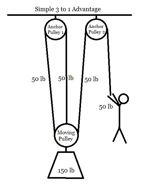
Progress Capture Prusik (installed on load side of anchor pulley)    (photo courtesy of rope-access.co.jp)

5:1  Fiddle Block/Block and Tackle setup

The 5:1 pulling system is probably the most versatile means of amplifying input forces in tree work. It can be used any time we need to generate maximum force on a rope, including tensioning, lifting, pulling, etc. This system really shines when your ground crew is limited in size, i.e. when there are only 1 or 2 people available to do the pulling.

A 5:1 system differs from the rest that we have seen because it is stored pre-built, i.e. you don’t put it together each time to use it. It consists of a spliced rope, 2 double pulleys, 2 carabiners, a progress capture, and a prusik cord for attaching to a load line. The rope of the 5:1 “begins” at the becket on the moving pulley, then goes twice through both pulleys before exiting at the moving pulley. In this way, you end up with 5 legs of rope acting on the moving pulley. It is hard to show all 5 legs of line with these simple drawings but it looks something like this:

This setup differs from the Z-Rig setup in that the actual rope attached to the load does not integrate into the MA system. Here the 5:1 attaches to the load line and then the rest of the load line just sits slack on the ground. Note that if you were to set this up backwards (i.e. such that stickman’s pull line exited from the anchor side of things) then the moving pulley would only have 4 legs of rope acting on it, and so this would be a 4:1 setup. So remember, with block and tackle systems, whenever possible, you want to set them up so that your pull is in a direction opposing the load, instead of in the direction of the load. This concept is referred to as “reeving to advantage”.

As far as names are concerned, I have been known to use the term “fiddle block” interchangeably with “5 to 1” or “block and tackle”, because they work the exact same way and they really are the same thing. Technically, a fiddle block is just a specially designed double pulley where the 2 sheaves are different size, with the smaller sheave sitting “inside” the larger sheave, which causes the 4 legs of rope to run “inline” through the system, as opposed to running side by side each other. Also, most fiddle block systems use cams for a progress capture while most block and tackle setups will use a prusik for that purpose. So, cosmetically they are a little different, but mechanically they are the same.

Fiddle Block system (photo courtesy westechrigging.com)
(progress capture cam is top left, where rope exits)
Standard Block and Tackle 5:1 system (photo courtesy arbtalk.co.uk)(note the progress capture prusik – blue rope)

Piggyback/Compound MA Systems

The final aspect of mechanical advantage that I want to touch on is what I call Piggyback systems. The basic concept here is that you can set up a primary MA system (usually a 2:1 or 3:1) and then attach a secondary MA system to act on the output line of the primary setup. In this way, the systems will multiply together to greatly amplify the resulting pull. For instance, if you were to build a 3:1 MA system and then attach another 3:1 MA system onto the end of it, the result would be 3 x 3 = 9:1 mechanical advantage! So this 9:1 system could be built with just 4 single pulleys, or it could also be built with a double pulley at the anchor and two single moving pulleys. Here’s what that might look like in stickman land:

Hopefully you can see the concept I am trying to convey with this kindergarten-quality picture. We have one 3:1 pulling directly on another 3:1 which multiplies the resultant output force to give us a 9:1 advantage! So for every pound of pull exerted by stickman, there are 9 pounds of force pulling on the load, but, for stickman to move the load 1 foot, he has to move 9 feet of rope through the system! The 9:1 setup shown above is only one of many compound MA systems that you can design once you understand all of the basic concepts that we have talked about. As with all of the MA setups that we have looked at, you must consider your anchor points when designing piggyback systems – they can be exposed to one hell of a load.


Conclusion

So, let’s return to the example way back at the beginning. Hopefully you can see that through the use of ropes and pulleys, our single groundman, now thoroughly educated in the ways of mechanical advantage, should be able to generate a 500 lb pull quite easily. All it takes is a solid grounding in the Basics, along with the right tools and equipment. Indeed, a groundman able to design and operate complex mechanical advantage systems such as these would be a highly valuable asset to any tree crew.

Thank you for sticking around to the end of another long-winded article. I really didn’t know it would run this long until I got right into the weeds, but I think it turned out really good. To paraphrase Blaise Pascal, “this one is longer than usual, because I had not time to make it shorter.” Thanks for listening. Now, heave ho!


Climb high, Work smart, Read more.
– TreeMuggs


I would love to hear from you. Please send all comments/questions/hatemail to patrick@educatedclimber.com


Filed Under: Back To Basics

  • « Previous Page
  • 1
  • …
  • 6
  • 7
  • 8
  • 9
  • 10
  • 11
  • Next Page »
  • The Manifesto
  • Subscribe to EducatedClimber
  • EducatedClimber on Youtube
  • Disclaimer
  • Amazon Affiliates Disclosure Page

Copyright © 2025 — Educated Climber.com • All rights reserved.